|
||||||||||
|
Model Code - top 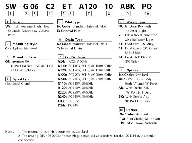 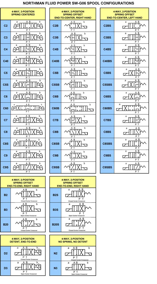 |
|||||||||||||||||||||||||||||||||||||||||||||||||||||||||||||||||||||||||||||||||||||||||||||||||||||||||||||||||||||||||||||||||||||||||||||||||||||||||||||||||||||||||||||||||||||||||||||||||||||||||||||||||||||||||||||||||||||||||||||||||||||||||||||||||||||||||||||||||||||||||||||||||||||||||||||||||||||||||||||||||||||||||||||||||||||||||||||||||||||||||||||||||||||||||||||||||||||||||||||||||||||||||||||||||||||||||||||||||||||||||||||||||||||||||||||||||||||||||||||||||||||||||||||||||||||||||||||||||||||||||||||||||||||||||||||||||||||||||||||||||||||||||||||||||||||||||||||||||||||||||||||||||||||||||||||||||||||||||||||||
|
Specifications - top
Option ET - top 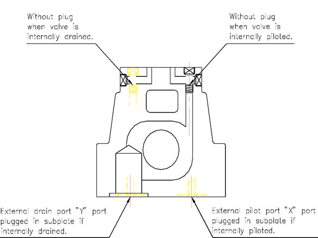 Solenoid Ratings - top
TECHNICAL DATA: • Solenoid can be used within -10% to +10% of the rated voltage of the coil. • Withstand voltage 1500 v/sec. • Insulation resistance over 100MQ. • A momentary signal of approx. 0.1 second is required for shifting action. • Pilot pressure of internally drained valves must always exceed tank port pressure by a minimum of 3.5 BAR (50 PSI) Valve must be externally drained if there is a possibility of tank line pressure surges overcoming this differential. • If the hydraulic circuit does not provide sufficient pilot pressure to shift valves with open center spool configurations C3, C5, C6, C60, do either: (1) Use the external pilot option (“-E-“). Provide 50 PSI (3.5 Bar) minimum pilot pressure to the “X” port on the manifold or subplate from another source in your system to shift the valve. (2) If the valve must be internally piloted in your system, then install back pressure of 50 PSI (3.5 Bar) minimum at the tank line of the main valve. The valve must be externally drained (“-T-“) with this method. ACCESSORIES: • Mounting bolt kits are supplied with valve socket head cap screws M12x60L 6 pcs (1/2"-13UNC-2Bx2 - 3/8"L 6 pcs) for tightening torque 1000-1230 kgf-cm (886 1066 lbs-in). • O-Ring P28 90° 4 pcs and P21 90° 2 pcs. List of Spool Functions
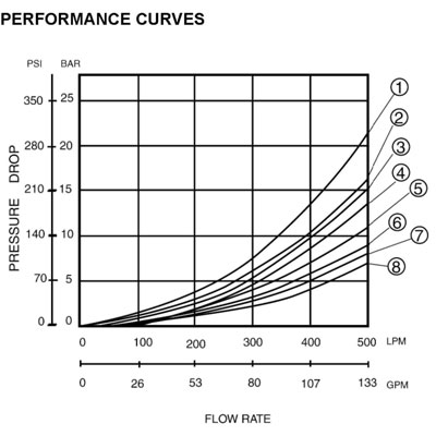
PRESSURE DROP AND PERFORMANCE CURVES
|
|||||||||||||||||||||||||||||||||||||||||||||||||||||||||||||||||||||||||||||||||||||||||||||||||||||||||||||||||||||||||||||||||||||||||||||||||||||||||||||||||||||||||||||||||||||||||||||||||||||||||||||||||||||||||||||||||||||||||||||||||||||||||||||||||||||||||||||||||||||||||||||||||||||||||||||||||||||||||||||||||||||||||||||||||||||||||||||||||||||||||||||||||||||||||||||||||||||||||||||||||||||||||||||||||||||||||||||||||||||||||||||||||||||||||||||||||||||||||||||||||||||||||||||||||||||||||||||||||||||||||||||||||||||||||||||||||||||||||||||||||||||||||||||||||||||||||||||||||||||||||||||||||||||||||||||||||||||||||||||||
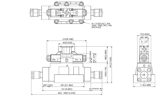
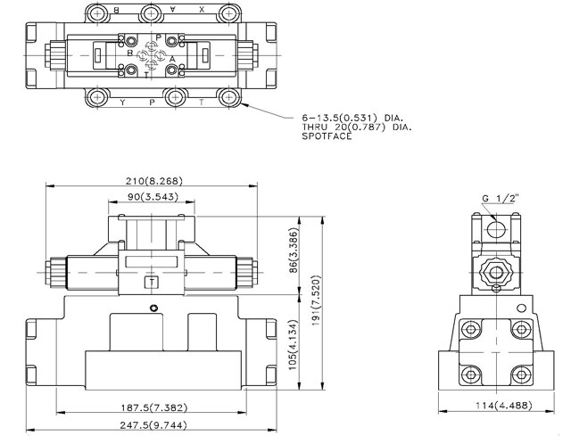
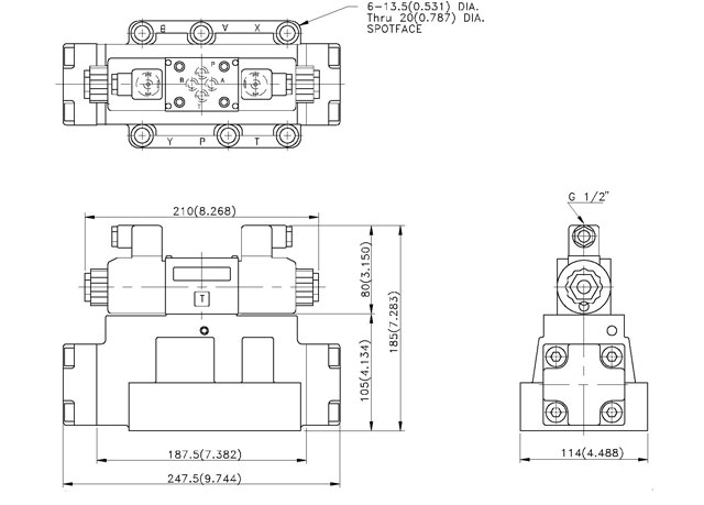
Dimensions - top SW - G06 - ** - **** - 10 |
MOUNTING
SURFACE: ISO 4401-AB-03-4-A UNIT: mm( inch) |
||||||||||||||||||||||||||||||||||||||||||||||||||||||||||||||||||||||||||||||||||||||||||||||||||||||||||||||||||||||||||||||||||||||||||||||||||||||||||||||||||||||||||||||||||||||||||||||||||||||||||||||||||||||||||||||||||||||||||||||||||||||||||||||||||||||||||||||||||||||||||||||||||||||||||||||||||||||||||||||||||||||||||||||||||||||||||||||||||||||||||||||||||||||||||||||||||||||||||||||||||||||||||||||||||||||||||||||||||||||||||||||||||||||||||||||||||||||||||||||||||||||||||||||||||||||||||||||||||||||||||||||||||||||||||||||||||||||||||||||||||||||||||||||||||||||||||||||||||||||||||||||||||||||||||||||||||||||||||||||
  |
|||||||||||||||||||||||||||||||||||||||||||||||||||||||||||||||||||||||||||||||||||||||||||||||||||||||||||||||||||||||||||||||||||||||||||||||||||||||||||||||||||||||||||||||||||||||||||||||||||||||||||||||||||||||||||||||||||||||||||||||||||||||||||||||||||||||||||||||||||||||||||||||||||||||||||||||||||||||||||||||||||||||||||||||||||||||||||||||||||||||||||||||||||||||||||||||||||||||||||||||||||||||||||||||||||||||||||||||||||||||||||||||||||||||||||||||||||||||||||||||||||||||||||||||||||||||||||||||||||||||||||||||||||||||||||||||||||||||||||||||||||||||||||||||||||||||||||||||||||||||||||||||||||||||||||||||||||||||||||||||
|
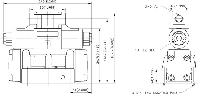
Dimensions - top SW - G06 - *** - **** - 20 |
MOUNTING
SURFACE: ISO 4401-AB-03-4-A UNIT: mm( inch) |
![]()
|
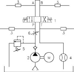
Dimensions - top SW - G06 - *** - **** - 10 -AB-K |
MOUNTING
SURFACE: ISO 4401-AB-03-4-A UNIT: mm( inch) |