|
|
|
|
 |
||
|
|
|
|
|
|
|
|
Quick Links
Model Code Specifications Dimensions |
||
|
|
|
|
||||||||||
|
Model Code - top 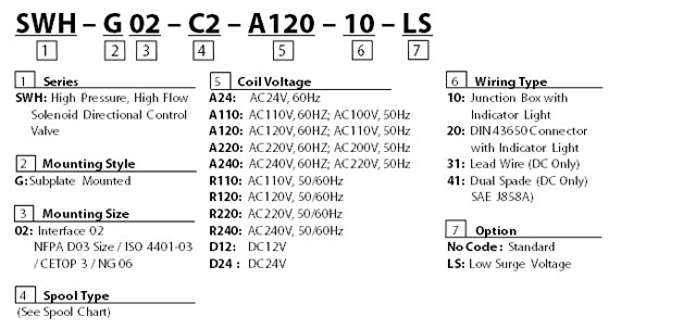  |
|||||||||||||||||||||||||||||||||||||||||||||||||||||||||||||||||||||||||||||||||||||||||||||||||||||||||||||||||||||||||||||||||||||||||||||||||||||||||||||||||||||||||||||||||||||||||||||||||||||||||||||||||||||||||||||||||||||||||||||||||||||||||||||||||||||||||||||||||||||||||||||||||||||||||||||||||||||||||||||||||||||||||||||||||||||||||||||||||||||||||||||||||||||||||||||||||||||||||||||||||||||||||||||||||||||||||||||||||||||||||||||||||||||||||||||||||||||||||||||||||||||||||||||||||||||||||||||||||||||||||||||||||||||||||||||||||||||||||||||||||||||||||||||||||||||||||||||||||||||||||||||||||||||||||||||||||||||||||||||||||||||||||||||||||||||||||||||||||||||||||||||||||||||||||||||||||||||||||||||||||||||||||||||||||||||||||||||||||||||||||||||||||||||||||||||||||||||||||
|
Specifications - top
Solenoid Ratings - top
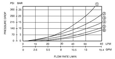
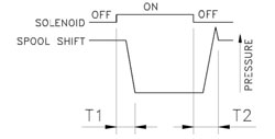
TECHNICAL DATA: - top • Solenoid can be used within -10% to +10% of the rated voltage of the coil. • Withstand voltage 1500 v/sec. • Insulation resistance over 100mQ • Conforms to rating IP65 • A momentary signal of approx 0.1 second is required for shifting action. ACCESSORIES: - top • Mounting bolt kits are supplied with valve socket head cap screws (#10-24UNCx1-3/4"L 4 pcs) for tightening torque 50-70 kgf-cm (43.3-60.6 lb-in). • O-Ring AS568-012 4 pcs. PRESSURE DROP AND PERFORMANCE CURVES - top
NOTE:
1. The figures in the square show the flow under saturated temperature and 90% rated voltage. 2. The upper number in table describes the maximum flow under DC and R. the lower number in table describes the maximum flow under AC. TEST SYSTEMS- top 1. Testing Valve 2. Pump 3. Pressure Sensor 4. Flow Sensor 5. Relief Valve 6. Throttle Valve TEST CONDITIONS Pressure: 138 BAR (2000PSI) Flow Rate: 30 LPM(8 GPM) Viscosity: 35 cSt(175 SSU) TEST CIRCUIT 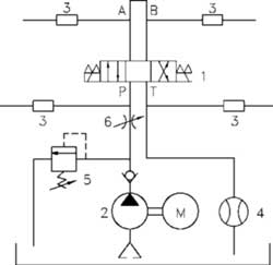
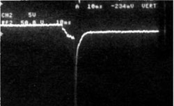
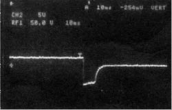
OPTION LS- top ELECTRICAL SURGE CONTROL MODEL SWH - G02 - *** - D ** - ** - LS FEATURES • Suppresses the surge voltage. • Eliminates sparks between relay contacts. • Extends the life of the relay contact. EFFECTS • Improves the reliability of the control relay. • Extends the life of conventional relays. • Can be operated with a miniature relay. • The RAC rectifier built-in DC model eliminates sparks at the control relay contact. It can be directly operated with a PLC (programmable logic controller).
|
|||||||||||||||||||||||||||||||||||||||||||||||||||||||||||||||||||||||||||||||||||||||||||||||||||||||||||||||||||||||||||||||||||||||||||||||||||||||||||||||||||||||||||||||||||||||||||||||||||||||||||||||||||||||||||||||||||||||||||||||||||||||||||||||||||||||||||||||||||||||||||||||||||||||||||||||||||||||||||||||||||||||||||||||||||||||||||||||||||||||||||||||||||||||||||||||||||||||||||||||||||||||||||||||||||||||||||||||||||||||||||||||||||||||||||||||||||||||||||||||||||||||||||||||||||||||||||||||||||||||||||||||||||||||||||||||||||||||||||||||||||||||||||||||||||||||||||||||||||||||||||||||||||||||||||||||||||||||||||||||||||||||||||||||||||||||||||||||||||||||||||||||||||||||||||||||||||||||||||||||||||||||||||||||||||||||||||||||||||||||||||||||||||||||||||||||||||||||||
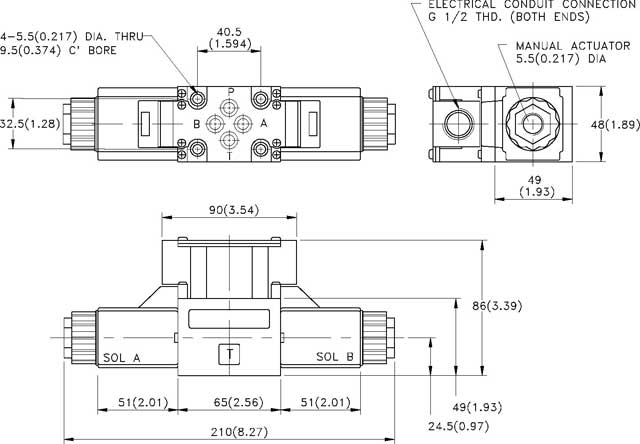
Dimensions - top SWH - G02 - C ** - **** - 10 - ** with AC/DC/RF solenoids |
MOUNTING
SURFACE: ISO 4401-AB-03-4-A UNIT: mm( inch) WEIGHT: 2.0 kgs (4.4 lbs) |
||||||||||||||||||||||||||||||||||||||||||||||||||||||||||||||||||||||||||||||||||||||||||||||||||||||||||||||||||||||||||||||||||||||||||||||||||||||||||||||||||||||||||||||||||||||||||||||||||||||||||||||||||||||||||||||||||||||||||||||||||||||||||||||||||||||||||||||||||||||||||||||||||||||||||||||||||||||||||||||||||||||||||||||||||||||||||||||||||||||||||||||||||||||||||||||||||||||||||||||||||||||||||||||||||||||||||||||||||||||||||||||||||||||||||||||||||||||||||||||||||||||||||||||||||||||||||||||||||||||||||||||||||||||||||||||||||||||||||||||||||||||||||||||||||||||||||||||||||||||||||||||||||||||||||||||||||||||||||||||||||||||||||||||||||||||||||||||||||||||||||||||||||||||||||||||||||||||||||||||||||||||||||||||||||||||||||||||||||||||||||||||||||||||||||||||||||||||||
 |
|||||||||||||||||||||||||||||||||||||||||||||||||||||||||||||||||||||||||||||||||||||||||||||||||||||||||||||||||||||||||||||||||||||||||||||||||||||||||||||||||||||||||||||||||||||||||||||||||||||||||||||||||||||||||||||||||||||||||||||||||||||||||||||||||||||||||||||||||||||||||||||||||||||||||||||||||||||||||||||||||||||||||||||||||||||||||||||||||||||||||||||||||||||||||||||||||||||||||||||||||||||||||||||||||||||||||||||||||||||||||||||||||||||||||||||||||||||||||||||||||||||||||||||||||||||||||||||||||||||||||||||||||||||||||||||||||||||||||||||||||||||||||||||||||||||||||||||||||||||||||||||||||||||||||||||||||||||||||||||||||||||||||||||||||||||||||||||||||||||||||||||||||||||||||||||||||||||||||||||||||||||||||||||||||||||||||||||||||||||||||||||||||||||||||||||||||||||||||
|
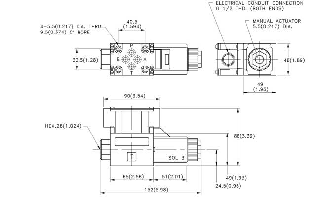
Dimensions - top SWH - G02 - B ** - **** - 10 - ** with AC/DC/RF solenoids |
MOUNTING
SURFACE: ISO 4401-AB-03-4-A UNIT: mm( inch) WEIGHT: 2.0 kgs (4.4 lbs) |
![]()
|
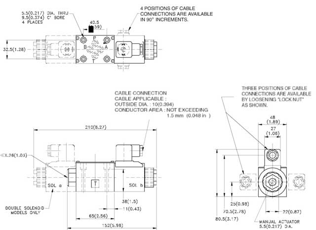
Dimensions - top SWH - G02 - *** - **** - 20 - ** with AC/DC/RF solenoids |
MOUNTING
SURFACE: ISO 4401-AB-03-4-A UNIT: mm( inch) |
![]()
Model and Weight - top
| MODEL | WEIGHT | MODEL | WEIGHT |
| kg(lb) | kg(lb) | ||
| SWH-G02-C **-A***-10-** | 1.9(4.18) | SWH-G02-C -A ***-20- ** | 1.9(4.18) |
| SWH-G02-B **- A***-10-** | 1.6(3.52) | SWH-G02-B- A***-20-** | 1.5(3.3) |
| SWH-G02-C**- D/R***-10-** | 2.0(4.4) | SWH-G02-C - D/R ***20-** | 2.0(4.4) |
| SWH-G02-B**- D/R**-10-** | 1.6(3.52) | SWH-G02-B - D/R ***-20- ** | 1.6(3.52) |
| SWH-G02-D **- A ***-10-** | 1.9(4.18) | SWH-G02-D- A ***-20- ** | 1.9(4.18) |
| SWH-G02-D**-D/R ***-10-** | 1.9(4.18) | SWH-G02-D - D/R *** -20-** | 1.9(4.18) |