|
|
||||||||||||||||||
|
Hydraulic Circuit Examples
Directional Control Valve and Subplate
Directional Control Valve, One Module and Subplate
Directional Control Valve, Two Modules and Subplate
The following circuit examples show typical mountings of a Northman directional
control valve to a subplate with and without modular valves.
Note: A complete hydraulic circuit is not shown. Hydraulic circuits vary widely
depending
on the functional purposes for which they are designed. The following examples
show
only the mounting of a Northman Fluid Power directional control valve and its
modular
valve accessories to a subplate in a typical cylinder control application. As
always, the
circuit designer must adhere to standard fluid power design practices to ensure
proper
pressure control and safety.
![]()
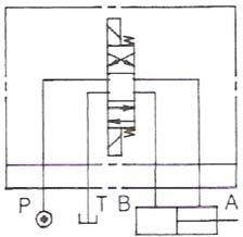 |
Circuit #1 Directional Control Valve and Subplate This circuit shows a directional control valve mounted to a subplate and controlling a cylinder. Any spool style may be used with this mounting style. |
|
|
|
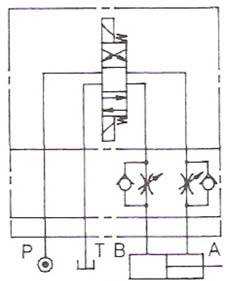 |
Circuit #2 Directional Control Valve, Flow Control Valve and Subplate This circuit shows a directional control valve mounted with a flow control modular valve to a subplate and controlling a cylinder. Any spool style may be used with this mounting style. |
|
|
|
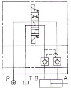 |
Circuit #3 Directional Control Valve, Pilot-Operated Check Valve and Subplate This circuit shows a directional control valve mounted with a pilot-operated check valve modular valve to a subplate and controlling a cylinder. The directional control valve must have the C4 “Float Center Spool” for this mounting combination to function properly because the pilots must be vented in order for the checks to be fully seated. |
|
|
|
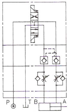 |
Circuit #4 Directional Control Valve, Pilot-Operated Check Valve, Flow Control Valve and Subplate This circuit shows a directional control valve mounted with a pilot-operated check valve modular valve and a flow control modular valve to a subplate and controlling a cylinder. The modules must be installed in this order and the directional control valve must have the C4 “Float Center Spool” for this mounting combination to function properly because the pilots must be vented in order for the checks to be fully seated. |